- 6th km Harilaou - Thermis, Thessaloniki, Greece

Pilot Plant Units
PETROCAT has access to the following equipment of LEFH
01 · Pilot Plant Units
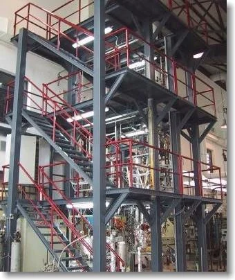
A riser based continuous pilot plant unit for catalytic cracking
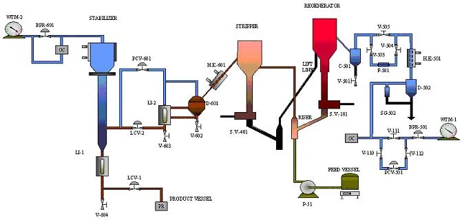
A schematic diagram of the fully automated FCC pilot plant is shown in the figure below. Preheated gas oil feed flows in the bottom of a riser, where it is mixed with hot regenerated catalyst. In the riser the reactions take place and at the riser exit, the mixture flows into the stripper vessel where the separation of gases from the solid catalysts occurs. The solids flow through the spent catalyst lift line and they return to the reactor bottom following regeneration.
The reaction products, from the stripper exit, flow through a heat exchanger where their temperature is reduced to 20 °C in order to condense the heavier products. The mixture is then led to a stabilizer column for better separation of liquid and gaseous products. The specifications of the CPERI pilot plant are shown in the table below.
| Pilot plant specifications and operating conditions | |
|---|---|
| Riser id (mm) and height (cm) | 7.08 / 165 |
| Regenerator bed id (mm) and height (cm) | 77.9 / 72 |
| Stripper id (mm) and height (cm) | 26.6 / 150 |
| Lift line id (mm) | 9.45 |
| Maximum liquid feed rate, g/min | 25 |
| Catalyst circulation rate, g/min | 35 – 500 |
| Maximum reactor pressure, atm | 3.3 |
| Max riser temperature, °C | 590 |
| Max stripper temperature, °C | 590 |
| Max regenerator temperature, °C | 700 |
| Catalyst inventory, g | 4500 |
02 · Catalyst Deactivation
Steamer unit for pilot scale samples
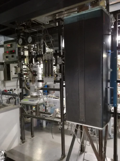
Two steamer units are available in LEFH for fresh FCC catalyst deactivation. Apart from steaming, the units can also be used as calcination units for the evaluation of equilibrium FCC catalysts. Each unit consists of a quartz fluid bed reactor heated by a 3-zone furnace. Temperature control is achieved with measurements from a thermocouple in the catalyst bed.
The one steamer is 75 cm high with a 6 cm diameter and accepts 150 g of fresh catalyst, while the second steamer accepts 3–5 kg of catalyst. The usage of each unit depends on the forthcoming step for catalyst evaluation (MAT or FCC pilot plant respectively). When used as a steamer, the fluidization stream is steam at 1450 °F; during calcination the fluidization stream is air at 1005 °F. The units are fully automated and steaming or calcination can be terminated after a desired period of time.
2steamer units
150 gsmall unit capacity
3–5 kglarge unit capacity
1450 °Fsteaming temperature
1005 °Fcalcination temperature
3-zonefurnace heating
03 · Catalyst Deactivation
Cyclic Propylene Steaming (CPS) deactivation for pilot scale samples
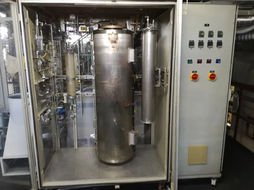
The reaction unit consists of the feed gas system, a fixed- and a fluidized-bed reactor, two three-zone furnaces controlled by PID controllers, one for each type of reactor, and the gas analysis system. The fixed- and fluidized-bed reactors are connected in series and can be bypassed by the feed.
Samples from the exit gas stream are analyzed with a series of gas analyzers to identify the gas products during regeneration.
| Typical experimental conditions | |
|---|---|
| Fixed-bed: inlet gas flow rate | 500 ml/min |
| Fixed-bed: reactor loading | 2 g |
| Fluidized-bed: inlet gas flow rate | 1000 ml/min |
| Fluidized-bed: reactor loading | 10 g |
04 · Catalyst Deactivation
Continuous cyclic deactivation unit (CDU) for pilot scale samples
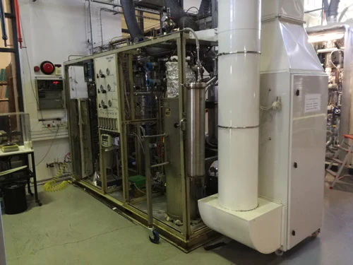
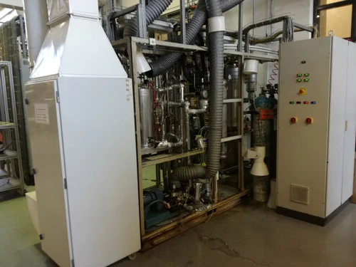
The CPERI cyclic deactivation unit (CDU), designed by Xytel, is fully computerized and satisfactorily simulates E-cats by depositing metals on FCC catalysts. This laboratory method is considered to be the most widely accepted for FCC catalyst aging. The CDU mimics FCC catalyst deactivation in repeated cycles of cracking, stripping and regeneration.
LEFH follows a specific protocol where a complete CDU run consists of 54 cycles, each one including a cracking, a stripping and a regeneration step and lasting about 60 minutes. Regeneration is achieved with a mixture of O2 and N2.
54cycles per run
~60 minper cycle
500 °C · 50 scracking step
500 °C · 180 sstripping with N2
788 °C · 2580 sregeneration
Xytelunit design
05 · Biomass Upgrading
A retort unit for studies related to the upgrading of biomass for bio-fuels and production of organic chemicals
A retort unit is available for studies related to the upgrading of biomass for bio-fuels and the production of organic chemicals.
06 · Hydroprocessing
A two stage high pressure hydrogen processing pilot plant
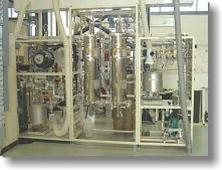
The two stage high pressure hydrogen processing pilot plant is built around two reactors operating in series, supported by independent gas and liquid delivery, sampling, gas outlet and separation modules. The unit process specifications are reported in the table below, followed by a description of each module.
| HDS-1 – Process specifications | |
|---|---|
| Number of reactors in series | 2 |
| Reactor volume, cc | 265 |
| Reactor diameter, inches | 2 |
| Reactor length, inches | 75 ½ |
| Catalyst bed length, inches | 18 |
| Operating pressure, barg | 280 |
| Operating temperature, max °C | 550 |
| Liquid feed rate, ml/h | 30 – 600 |
| Gas rate, Nl/h | 100 – 1000 |
Reactor module
Two reactors operating in series, each with a radiation split-type furnace. The catalyst volume (middle part of the reactor) can be widely varied by adding more or less inerts. Both reactors can be used in series for up and down flow, and an extra “swing pipe” can by-pass the second reactor.
Gas delivery modules
Three independent gas feed modules with all necessary equipment. Hydrogen, nitrogen or a mix of hydrogen/H2S can be used as feed gas.
Liquid delivery module
Oil is contained in a nitrogen-blanketed vessel on a weigh scale, with electrical heating under automatic temperature control. The pre-sulfiding liquid is contained in a nitrogen-blanketed vessel.
Sampling module
A sample of the product at the separator outlet can be taken via a pneumatically actuated three-way valve.
Gas outlet module
A pressure control section maintains the required reactor pressure, with a by-pass for atmospheric operation. Outlet lines are heat traced and insulated, and the outlet vent is connected to a wet test meter.
Separation & liquid outlet
A pipe-in-pipe cooler cools the reactor outlet product. The separator has a narrow electrically heated liquid part and a wide water-cooled gas part. Product is collected in a heated vessel on a weigh scale.